All-In-One OpenStack Liberty using RDO Packstack with External Public IPs

Summary

This is a single node, proof-of-concept that includes setting up the external connectivity to your VMs (aka, “instances” in OpenStackian lingo). It uses the RDO tool Packstack and will install the Liberty release of OpenStack. You will have full access to an instance from outside the OpenStack environment via its Public floating IP. This guide uses the VXLAN provider, so it should work in multi-node configurations. The current RDO documentation for Public floating IPs uses the FLAT provider, which only works for a single node. I wrote this article because I had to follow 3-4 different guides to get here and figured others might like all of this information compiled into one guide.

TIP: I highly recommend using a virtual system (aka, VirtualBox) for the setup, at least initially. OpenStack works well running inside another virtual environment; the benefits of snapshots/clones/virtual nics will make your experiments and testing much easier. I’ll provide specifics for using VirtualBox with this guide, alongside the non-virtual instructions.

Example Setup

Scenario 1: OpenStack VM Running Inside VirtualBox

This diagram shows the architectural layout, assuming you run it inside a VirtualBox VM.

All-in-One Architecture

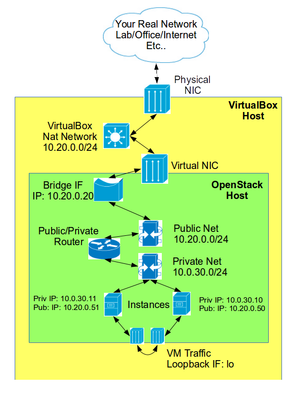
Architecture inside of VirtualBox VM

OpenStack will be run from inside a VM, on a computer running VirtualBox. Network connectivity for the VM will be provided by the NAT Network in Virtualbox. The downside to using a NAT Network instead of a Bridge Interface is that the OpenStack instance public IPs will only be public to other VirtualBox VMs. I chose a NAT Network interface because OpenStack needs a static IP to operate and a NAT Network guarantees that. In my case, I kept breaking my OpenStack install because I would take my laptop home and all the IPs would change when I connected there. If your VirtualBox host will always remain attached to the same network, then feel free to use a Bridge Interface for your OpenStack VM, which would allow OpenStack, and its instances, to have true public IPs.

Scenerio 2: OpenStack Running Directly on Hardware

This diagram is the same as before, just without the VirtualBox VM sandbox. OpenStack public IPs will be real ones from your Office/Lab/Internet network.

All-in-One Physical Architecture

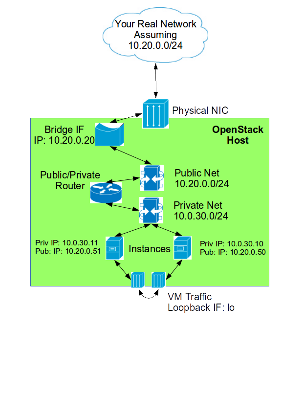
Architecture For Baremetal Install

Meet the Networks

External Network

The external network is the outside network. For an all-in-one install, you use this network for external and OpenStack API traffic. your public IPs will use this network to communicate with the outside world (virtual and real). For the VirtualBox Scenario, this will be the NAT Network. For the Physical Scenario, this will be your Office/Lab/Internet. This is the network your NIC will be physically attached to.

*Note: We’re using your external interface for your private OpenStack API traffic. In an all-in-one, the API traffic will never leave the public interface because it’s always pointed at its own IP and will therefore loop back. Multi-node installs should have a separate private network for API communication, as it really should be kept off the public interface. However, most of the service will be listening on the external IP; so if you want to use “keystone,” for example, from another machine on the network, you can. *

In your example we’ll assume your external network is setup like this:

  • Subnet: 10.20.0.0/24
  • Netmask: 255.255.255.0
  • Gateway: 10.20.0.1
  • DNS1: 8.8.8.8
  • DNS2: 8.8.4.4
  • public IP Range: 10.20.0.50 – 10.20.0.254
    FYI: The DNS 8.8.8.8 and 8.8.4.4 are google-provided DNS servers that work everywhere.

Private Network

The private network is what the instances are connected to. All instance traffic will go though the private network. In an all-in-one box, the private interface is just the loopback device “lo,” since all the instances are located on the same machine. Traffic headed out to the external network will start on the private network and then route to the public network via a virtual router inside of OpenStack (neat!!… once it all works).

In your example, we’ll assume your private network is setup like this:

  • Subnet: 10.0.30.0/24
  • Netmask: 255.255.255.0
  • Gateway: 10.0.30.1
  • DNS1: 8.8.8.8
  • DNS2: 8.8.4.4
  • public IP Range: 10.0.30.10 – 10.0.30.254

VirtualBox Setup

If you’re going to do this inside VirtualBox, here’s what you should do to setup your environment:

NAT Network Setup

In order to provide a stable network in your virtual environment, we’re going to setup a NAT Network. This is a combination of an internal network and a NAT, so that it can access the outside world. We’re doing this so that your OpenStack server will always have a consistent IP (10.20.0.20), no matter what network your physical machine is connected to. I was doing my testing on a laptop that I would transfer between work and home, which meant that my networks would change.

Note: If you want OpenStack to have a real physical IP, and your physical machine isn’t going to be changing networks, then you can skip this and just attach the virtual NIC to a bridged adapter.

In VirtualBox Create a New NAT Network

  • Name: PubAIO
  • Network CIDR: 10.20.0.0/24
  • Supports DHCP: Unchecked
    Statically define your OpenStack VMs IP or you’ll have problems if its IP changes
  • Port Forwarding:
Name Protocol Host IP Host Port Guest IP Guest Port
SSH TCP 127.0.0.1 2022 10.20.0.20 22
HTTP TCP 127.0.0.1 2080 10.20.0.20 80

This will allow you to access the OpenStack VM from your physical machine via ssh and your web browser.

Virtual Machine Configuration

  • Name: osaio
  • Type: Linux
  • Red Hat (64-bit)
  • VCPUs: 1
  • Ram: 3GB Min 4GB recommended (2GB will only let you start two 128MB instances)
  • Storage: 10GB Storage (fixed size)
  • Network: 1Gb NIC
  • Attached to: NAT Network
  • Name: PubAIO
  • Adapter Type: Paravirtualized Network (virtio-net)
    This will provide better network performance
  • Promiscuous Mode: Allow All
    This allows the public IPs you will be creating to communicate via this NIC

Install VirtualBox Guest Additions for better performance (and less annoyance)

Setup a Workstation VM

You can use the NAT Port Forwarding rules to control your OpenStack VM. One exception will be the console connection to newly created instances. When you access the console from an instance, via the OpenStack web interface, it will redirect you to the OpenStack VM’s IP and a port assigned for that VNC session. Because we’re using Port Forwarding and accessing OpenStack via localhost on a forwarded port, the VNC session will break. The ugly way around this is to setup a workstation VM that can run a web browser and attach it to the PubAIO NAT Network. When you need to access the console for an instance, you will console into the workstation VM and through it, access the OpenStack web interface. Since it is inside the PubAIO NAT Network, the redirection for the instance’s console will work.
I’m not proud of this workaround, but it gets the job done.

Install OpenStack

OS Install

I did a minimal install of Centos 7.X, with a single large root partition using the entire 10GB of space. The minimal install auto-partitioner is pretty dumb, so make sure to select manual partitioning. Once selected, you’ll be given an option to autoconfig and review the proposed changes. Configure the host with the following system settings:

  • Partitions:
  • /boot 500MiB
  • /root 8672MiB
  • /swap 1024MiB
  • Network Type: Manual
  • IP: 10.20.0.20
  • NetMask: 255.255.255.0
  • Gateway: 10.20.0.1
  • DNS: 8.8.8.8
  • Root Password: 0p3n5t4cK
  • Hostname: osaio

Once install is finished, confirm the VM can access the internet

root@vm:~$ ping pingdom.com

Test the port forwarding

user@workstation:~$ ssh root@localhost -p 2022
root@osaio

Install OpenStack Prerequisites

  1. Make sure your environment has sane defaults
    root@osaio:~$ vi /etc/environment
    LANG=en_US.utf-8
    LC_ALL=en_US.utf-8
    
  2. Install the RDO repo
    root@osaio:~$ yum install -y https://www.rdoproject.org/repos/rdo-release.rpm
    
  3. Install the EPEL repo
    root@osaio:~$ yum install -y https://dl.fedoraproject.org/pub/epel/epel-release-latest-7.noarch.rpm
    
  4. Make sure all packages are current
    root@osaio:~$ yum -y upgrade
    
  5. Install some nice utilities
    root@osaio:~$ yum install -y screen traceroute bind-utils
    
  6. Disable network manager (RDO doesn’t like it)
    root@osaio:~$ systemctl stop NetworkManager
    root@osaio:~$ systemctl disable NetworkManager
    root@osaio:~$ systemctl start network.service
    root@osaio:~$ systemctl enable network.service
    
  7. Install the Packstack installer and its utilities
    root@osaio:~$ yum install -y OpenStack-packstack OpenStack-utils
    
  8. Generate the initial answer file
    Note: This is easier to manage than Packstack command line options

    root@aionode:~$ packstack --gen-answer-file=allinone-answers.cfg
    
  9. Reboot to make sure you’re using the latest installed kernel, etc…
    root@aionode:~$ reboot
    
  10. Modify the answer file for your All-in-One install
    root@aionode:~$ vi /root/allinone-answers.cfg
    CONFIG_NTP_SERVERS=0.rhel.pool.ntp.org,1.rhel.pool.ntp.org
    CONFIG_DEFAULT_PASSWORD=0p3n5t4cK
    CONFIG_KEYSTONE_ADMIN_PW=0p3n5t4cK
    CONFIG_CINDER_VOLUMES_SIZE=4G
    CONFIG_NOVA_COMPUTE_PRIVIF=lo
    CONFIG_NOVA_NETWORK_PRIVIF=lo
    CONFIG_NEUTRON_OVS_BRIDGE_MAPPINGS=physnet1:br-ex
    CONFIG_PROVISION_DEMO=n
    CONFIG_NOVA_NETWORK_PUBIF=eth0
    CONFIG_NEUTRON_OVS_BRIDGE_IFACES=br-ex:eth0
    

Note: You can use the openstack-config utility to automate this in a script

Example:

openstack-config --set ~/allinone-answers.cfg general CONFIG_NTP_SERVERS 0.rhel.pool.ntp.org,1.rhel.pool.ntp.org
openstack-config --set ~/allinone-answers.cfg general CONFIG_DEFAULT_PASSWORD 0p3n5t4cK
openstack-config --set ~/allinone-answers.cfg general CONFIG_KEYSTONE_ADMIN_PW 0p3n5t4cK
openstack-config --set ~/allinone-answers.cfg general CONFIG_CINDER_VOLUMES_SIZE 4G
openstack-config --set ~/allinone-answers.cfg general CONFIG_NOVA_COMPUTE_PRIVIF lo
openstack-config --set ~/allinone-answers.cfg general CONFIG_NOVA_NETWORK_PRIVIF lo
openstack-config --set ~/allinone-answers.cfg general CONFIG_NEUTRON_OVS_BRIDGE_MAPPINGS physnet1:br-ex
openstack-config --set ~/allinone-answers.cfg general CONFIG_PROVISION_DEMO n
openstack-config --set ~/allinone-answers.cfg general CONFIG_NOVA_NETWORK_PUBIF eth0
openstack-config --set ~/allinone-answers.cfg general CONFIG_NEUTRON_OVS_BRIDGE_IFACES br-ex:eth0

Here is an explanation of the variables:

VARIABLE NAME VALUE DESCRIPTION
CONFIG_NTP_SERVERS 0.rhel.pool.ntp.org, 1.rhel.pool.ntp.org Time Servers to keep your time in sync (not required, but why not)
CONFIG_DEFAULT_PASSWORD 0p3n5t4cK Set default password for various services
CONFIG_KEYSTONE_ADMIN_PW 0p3n5t4cK Initial admin password for OpenStack
CONFIG_CINDER_VOLUMES_SIZE 4G How much space you’ll reserve for add-on volumes1
CONFIG_NOVA_COMPUTE_PRIVIF lo For the All-in-One Compute service, you use a loopback for your private network
CONFIG_NOVA_NETWORK_PRIVIF lo For the All-in-One network service, use a loopback for your private network
CONFIG_NOVA_NETWORK_PUBIF eth02 This should be the NIC on your VM/physical server that can reach the rest of the network
CONFIG_NEUTRON_OVS_BRIDGE_MAPPINGS physnet1:br-ex Mapping from the physical network name, physnet1, to the external bridge name, br-ex
CONFIG_NEUTRON_OVS_BRIDGE_IFACES br-ex:eth02 Similar to PUBIF, this automatically creates the bridge, br-ex, and transfers the eth0 config to it
CONFIG_PROVISION_DEMO n Don’t have Packstack provision a demo project. You'll be creating this manually with different values

Minimal OS for the Impatient (Optional)

These projects can be disabled, which will let the install go more quickly, but you will still have enough functionality to complete this guide.

openstack-config --set ~/allinone-answers.cfg general CONFIG_CINDER_INSTALL n
openstack-config --set ~/allinone-answers.cfg general CONFIG_SWIFT_INSTALL n
openstack-config --set ~/allinone-answers.cfg general CONFIG_CEILOMETER_INSTALL n
openstack-config --set ~/allinone-answers.cfg general CONFIG_NAGIOS_INSTALL n

Pre-Deploy Network

root@osaio:~$ ip a
1: lo: <LOOPBACK,UP,LOWER_UP> mtu 65536 qdisc noqueue state UNKNOWN
link/loopback 00:00:00:00:00:00 brd 00:00:00:00:00:00
inet 127.0.0.1/8 scope host lo
valid_lft forever preferred_lft forever
inet6 ::1/128 scope host
valid_lft forever preferred_lft forever
2: eth0: <BROADCAST,MULTICAST,UP,LOWER_UP> mtu 1500 qdisc pfifo_fast state UP qlen 1000
link/ether 08:00:27:1b:12:7d brd ff:ff:ff:ff:ff:ff
inet 10.20.0.20/24 brd 10.20.0.255 scope global eth0
valid_lft forever preferred_lft forever
inet6 fe80::a00:27ff:fe1b:127d/64 scope link
valid_lft forever preferred_lft forever

So before deployment, you have the loopback and your physical interface that is configured with an IP address. The CONFIG_NEUTRON_OVS_BRIDGE_IFACES will change this.

Install Time

Run RDO Packstack With the Answer File you Generated

root@aionode:~$ packstack --answer-file=allinone-answers.cfg

Note: This takes a while. Patience, go get a soda from the fridge. You should be seeing bunches of [ Done ] (red is bad). Sometimes just rerunning will clear an occasional red message.

Switch to Full SW Virtualization (VirtualBox Only)

If you’re installing OpenStack in a VirtualBox VM, you need to switch to full software virtualization to run instances.

  1. Reconfigure Nova to use qemu vs. kvm
root@aionode:~$ OpenStack-config --set /etc/nova/nova.conf DEFAULT libvirt_type qemu
  1. Restart services to apply the change
root@aionode:~$ systemctl restart OpenStack-nova-compute.service

#Review Networking

Post-Deploy Network

root@osaio:~$ ip a
1: lo: <LOOPBACK,UP,LOWER_UP> mtu 65536 qdisc noqueue state UNKNOWN
link/loopback 00:00:00:00:00:00 brd 00:00:00:00:00:00
inet 127.0.0.1/8 scope host lo
valid_lft forever preferred_lft forever
inet6 ::1/128 scope host
valid_lft forever preferred_lft forever
2: eth0: <BROADCAST,MULTICAST,UP,LOWER_UP> mtu 1500 qdisc pfifo_fast master ovs-system state UP qlen 1000
link/ether 08:00:27:1b:12:7d brd ff:ff:ff:ff:ff:ff
inet6 fe80::a00:27ff:fe1b:127d/64 scope link
valid_lft forever preferred_lft forever
3: ovs-system: <BROADCAST,MULTICAST> mtu 1500 qdisc noop state DOWN
link/ether aa:37:65:96:52:74 brd ff:ff:ff:ff:ff:ff
5: br-ex: <BROADCAST,MULTICAST,UP,LOWER_UP> mtu 1500 qdisc noqueue state UNKNOWN
link/ether 08:00:27:1b:12:7d brd ff:ff:ff:ff:ff:ff
inet 10.20.0.20/24 brd 10.20.0.255 scope global br-ex
valid_lft forever preferred_lft forever
inet6 fe80::a45b:5aff:fe0d:4e4a/64 scope link
valid_lft forever preferred_lft forever
6: br-int: <BROADCAST,MULTICAST> mtu 1500 qdisc noop state DOWN
link/ether 3e:bb:67:4f:b4:46 brd ff:ff:ff:ff:ff:ff
7: br-tun: <BROADCAST,MULTICAST> mtu 1500 qdisc noop state DOWN
link/ether fa:f9:5a:7a:68:4f brd ff:ff:ff:ff:ff:ff

So the IP address has moved from the physical interface eth0 to br-ex. Also several other bridges have been created: br-int,br-tun.

OpenVswitch Config

Right after the install finishes your bridge config should look like this:

[root@ostack ~]# ovs-vsctl show
96ab8860-e31e-4455-8376-09dc774f4304
Bridge br-ex
Port br-ex
Interface br-ex
type: internal
Port phy-br-ex
Interface phy-br-ex
type: patch
options: {peer=int-br-ex}
Port "eth0"
Interface "eth0"
Bridge br-int
fail_mode: secure
Port br-int
Interface br-int
type: internal
Port int-br-ex
Interface int-br-ex
type: patch
options: {peer=phy-br-ex}
Port patch-tun
Interface patch-tun
type: patch
options: {peer=patch-int}
Bridge br-tun
fail_mode: secure
Port patch-int
Interface patch-int
type: patch
options: {peer=patch-tun}
Port br-tun
Interface br-tun
type: internal
ovs_version: "2.4.0"

So you’ll notice that your bridge br-ex now has your NIC attached as a port. Think of the bridge as a switch and we’ve just attached your uplink, aka eth0.

The directive CONFIG_NEUTRON_OVS_BRIDGE_MAPPINGS created two new ports. On the external bridge br-ex the phy-br-ex port was created. On the internal bride br-int the int-br-ex port was created.

The directive CONFIG_NEUTRON_OVS_BRIDGE_IFACES created the br-ex interface and migrated the IP information from the physical interface eth0.

Almost There!!

At this point you should have a fully operational OpenStack All-in-One with external network connectivity. All that’s left to do is setup the environment for your projects inside OpenStack itself. The rest of this tutorial can be done from the web GUI (Horizon).

Accessing the Web-Interface

As mentioned above, the web interface is called Horizon. It allows you to administer many aspects of your OpenStack install, as well as provide a self-service web interface for your tenants.

Accessing Horizon From a VirtualBox Setup

If you’re using VirtualBox, you will be using one of the NAT rules you made as part of your NAT Network config. The URL is http://localhost:2080.

Accessing Horizon From a Physical Server Setup

If you’ve setup a physical OpenStack server, just access via its IP and not localhost. Example: http://{physical server}/.

The initial username is “admin” and the password is what you set in CONFIG_KEYSTONE_ADMIN_PW, aka “0p3n5t4cK”. RDO also stores the password in an environment script /root/keystonerc_admin.

Setup OpenStack Environment for Tenants

Install a Test Image

You’re going to upload a minimal Linux that you will use as a test instance later on.

  1. Login to Horizon as “admin”
  2. Select the “Admin” tab
  3. Select “Images” from the left-side menu
  4. Select “+ Create Image”
  5. Select “Create Image”

Create a Nano Flavor

Since your proof of concept is probably working in tight spaces, in terms of RAM/storage, you’re going to create a new flavor, to minimize the resources you use to launch your test instances. A flavor is a resource profile you apply when launching an instance.

  1. Select “Flavors” from the left-side menu
  2. Select “+ Create Flavor”
    • Name: m1.nano
    • ID: auto
    • VCPUs: 1
    • RAM MB: 128
    • Root Disk GB: 1
    • Ephemeral Disk GB: 0
    • Swap Disk MB: 0
  3. Select “Create Flavor”

Create a Project

This will be the project you use for testing. Technically an admin project is created but you really shouldn’t use this to setup user instances. OpenStack also calls projects Tenants.

  1. Select "Identity/Projects" from the left-site menu
  2. Select "Create Project"
    • Name "Demo Project"
    • Enabled "Checked"
  3. Select "Quota" Tab
    • Volumes "10"
    • Volume Snapshots "10"
    • Total Size of Volumes "5"

You'll see some errors: unable to set quotas and can't determine volume limit. Don't sweat it.

Create the Demo User

This will be the user you use for testing. They will be a member of the Demo project.

  1. Select “Identity/Users” from the left-side menu
  2. Select “+ Create User”
    • User Name: demo
    • Password: demo
    • Primary Project: Demo Project
    • Role: member
  3. Select “Create User”

Setup Internal OpenStack Network

Create Public Floating Network (All Tenants)

This is the virtual network that OpenStack will bridge to the outside world. You will assign public IPs to your instances from this network.

Web Interface Method

  1. Select “System/Networks” from the left-side menu
  2. Select “+ Create Network”
    • Name: public
    • Project: admin
    • Provider Network Type: VXLAN
    • Segmentation ID: 96
      I think this is an arbitrary number/just shouldn't conflict
    • External Network: Checked
  3. Select “Create Network”

CLI Method

root@aionode:~$ source /root/keystone_admin
root@aionode:~$ neutron net-create public --router:external=True --provider:network_type=vxlan --provider:segmentation_id=96

Results

Field Value
admin_state_up True
id ef430df2-5206-4b5f-b630-ef25176eb351
mtu 0
name public
provider:network_type vxlan
provider:physical_network
provider:segmentation_id 96
router:external True
shared False
status ACTIVE
subnets
tenant_id c6ed09fb7970466d994985571201e775

Create IP Range

Now that you’ve created the network, you need to add a range of IPs to be used as the floating IP pool.

Web Interface Method

  1. Select “System/Networks” from the left-side menu
  2. Under the "Network Name" column select "public"
    Clicking "Edit Network" takes you somewhere else
  3. Select "Create Subnet"
    • Name: public_subnet
    • Network Address: 10.20.0.0/24
    • IP Version: IPv4
    • Gateway: 10.20.0.1
    • Disable Gateway: Unchecked
  4. Select "Subnet Details"
    • Enable DHCP: Unchecked
    • Allocation Pools: 10.20.0.100,10.20.0.150
  5. Select “Create”

CLI Method

root@aionode:~(keystone_admin)$ neutron subnet-create --name public_subnet --disable-dhcp --allocation-pool start=10.20.0.100,end=10.20.0.150 public 10.20.0.0/24

Result

Field Value
allocation_pools {“start”: “10.20.0.100”, “end”: “10.20.0.150”}
cidr 10.20.0.0/24
dns_nameservers
enable_dhcp False
gateway_ip 10.20.0.1
host_routes
id 8ffd99c5-b6d9-4d46-ac5a-92b6e659f839
ip_version 4
ipv6_address_mode
ipv6_ra_mode
name public_subnet
network_id 267ee4a2-8e11-4bb1-8e46-a4cc89ad23e3
subnetpool_id
tenant_id c6ed09fb7970466d994985571201e775

Done with Setup from Admin Side!!

At this point you’re done with the setup of the environment from the administrative side. All that remains is to login as the tenant and do some final network setup.

Finish the Network Setup in the Demo Project

The rest of the configuration is done inside the project as the demo user. You’re going to add some virtual routers and a private subnet, so that your instances will have private IPs and a route to the OpenStack wide floating IP network.

Access the Demo Project

Logout of the web interface and log back in using the demo/demo credentials.

Once you login to the demo project, you’ll see a similar setup to when you were logged in as the admin. The admin tab is absent, of course, and so are a couple of the other options on the left-side menu.

Setup the Private Network (Tenant Specific)

In order to access the cli commands as the demo user, you need to create a shell script with their credentials.

Setup demo user environment script
1. Select “Compute/Access & Security” tab
2. Select “API Access”
3. Select “Download OpenStack RC file”
4. Copy contents to: root@aionode:~$ keystonerc_demo

Setup Tenant Network/Subnet

This is the private network your instances will attach to. Instances will be issued IPs from this private IP subnet.

Create Tenant Network

Web Interface Method

  1. Select “Network/Networks” from the left-side menu
  2. Select “Create Network”
    • Name: private
    • Create Subnet: checked
  3. Select “Subnet” tab
    • Subnet Name: private_subnet
    • Network Addresses: 10.0.30.0/24
    • IP Version: IPv4
    • Gateway IP: Default of 1st IP is fine so leave this blank
  4. Select “Subnet Details” tab
    • Allocation Pools: 10.0.30.50,10.0.30.100
    • DNS Name Servers:
    • 8.8.8.8
    • 8.8.4.4
  5. Select “Create”

CLI Method

root@osaio:~$ source /root/keystonerc_demo
root@osaio:(keystone_demo)$ neutron net-create private
root@osaio:(keystone_demo)$ neutron subnet-create --name private_subnet --dns-nameserver 8.8.8.8 --dns-nameserver 8.8.4.4 --allocation-pool start=10.0.30.10,end=10.0.30.254 private 10.0.30.0/24

Note: The prompt won’t actually display (keystone_demo) because the shell script doesn’t set it, but I’m using it here to indicate that you should be sourcing the demo users credentials.

Private Network Results
[root@osaio ~(keystone_admin)]# neutron net-show private

Field Value
admin_state_up True
id b018b8ac-002e-4ab9-bb60-2bd82f060728
mtu 0
name private
provider:network_type vxlan
provider:physical_network
provider:segmentation_id 54
router:external False
shared False
status ACTIVE
subnets 4009aae4-624a-4134-a0f4-05711278a6a7
tenant_id 3fa9a67f91e14f09a7b40a180e7a596c

Private Subnet Results
[root@osaio ~(keystone_admin)]# neutron subnet-show private_subnet

Field Value
allocation_pools {“start”: “10.0.30.50”, “end”: “10.0.30.100”}
cidr 10.0.30.0/24
dns_nameservers 8.8.8.8
8.8.4.4
enable_dhcp True
gateway_ip 10.0.30.1
host_routes
id 4009aae4-624a-4134-a0f4-05711278a6a7
ip_version 4
ipv6_address_mode
ipv6_ra_mode
name private_subnet
network_id b018b8ac-002e-4ab9-bb60-2bd82f060728
subnetpool_id
tenant_id 3fa9a67f91e14f09a7b40a180e7a596c

Create an External Router to Attach to floating IP Network

This router will attach to your private subnet and route to the public network, which is where your floating IPs are located.
Web Interface Method

  1. Select “Network/Routers” from the left-side menu
  2. Select “Create Router”
    • Name: extrouter
    • External Network: public
  3. Select “Create Router”
  4. Under the “Name” column select “extrouter”
  5. Select the “Interfaces” tab
  6. Select “Add Interface”
    • Subnet: private
  7. Select “Add Interface”

CLI Method

root@osaio:(keystone_demo)$ neutron router-create extrouter
root@osaio:(keystone_demo)$ neutron router-gateway-set extrouter public
root@osaio:(keystone_demo)$ neutron router-interface-add extrouter private_subnet

First Instance TEST

Login to dashboard http://node1/dashboard as the “demo” user.

Create a Keypair

This is used to ssh into your instances without a password.

  1. Login via web interface as the demo user
  2. Select “Compute/Access & Security/Keypairs
  3. Select “Create Keypair”
    • Key Pair Name: {{ userid }}_key
  4. Download the private key when prompted
    You’ll only get one shot at this. You can’t go back later and get this file again

Note: To use the private key in putty, you will have to load the pem file into puttygen and save as a ppk and then import into the sshagent.

Note: For OS X and linux just invoke ssh with -i pemfile.pem to login.

Setup Security Groups

The Security Groups are the equivalent to firewall rules in OpenStack. These rules will be applied to the interfaces of any instances you create in your tenant. You will open the ports for ssh and ping to the world. Obviously not a great idea to do this in a production environment. 😉

  1. Select “Compute/Access & Security”
  2. Select “Manage Rules” under “default” security group
  3. Select “Add Rule”
    • Rule: SSH
  4. Confirm with the “Add” button
  5. Select “Add Rule”
    • Rule: Custom ICMP
    • Type: -1
    • Code: -1
  6. Confirm with the “Add” button

Create/Launch the Instance

  1. Select “Compute/Instances”
  2. Select “Launch Instance”
    • Instance Name: CTest
    • Flavor: m1.nano
    • Instance Boot Source: Boot from image
    • Image Name: cirros
  3. Select the “networking” tab
    • Selected Networks: Private
  4. “Launch”

If you are doing this on physical hardware, you should be able to access the instance’s console now. If you’re in VirtualBox, you’ll need the Workstation VM on the 10.20.0.0 NAT Network with a GUI/web browser to access the console. Don’t sweat it if you can’t access the console because in the next step you’ll add a floating IP and will be able to access it that way.

Associate the Floating IP

  1. Select “Compute/Instances”
  2. Under “Actions” select “Associate floating IP”
  3. Select the “+” next to the IP Address
  4. Select “allocate IP”
  5. Select “Associate”
    You should see both public and private IP addresses listed in the “IP Address” column for your instance.

Now Test Floating IP

VirtualBox

Since you setup your All-In-One install in a NAT Network you need to add new rules to allow access from your workstation to the new instance.

  1. Select “VirtualBox/Preferences/Networking”
  2. Edit “PubAIO”
  3. Select “Port Forwarding”
Name Protocol Host IP Host Port Guest IP Guest Port
SSH INST1 TCP 127.0.0.1 3022 10.20.0.101 22

Note: This assumes that the floating IP you’re issued for your VM is “10.20.0.101” otherwise, fill it in with the correct value.

  1. ping the floating IP (From osaio console)
    root@osaio ~]# ping 10.20.0.101
    PING 10.20.0.101 (10.20.0.101) 56(84) bytes of data.
    64 bytes from 10.20.0.101: icmp_seq=1 ttl=63 time=1.25 ms
    64 bytes from 10.20.0.101: icmp_seq=2 ttl=63 time=0.503 ms
    64 bytes from 10.20.0.101: icmp_seq=3 ttl=63 time=0.904 ms
    
  2. ssh into instance (From your workstation using the VirtualBox floating IP)
    user@workstation ~$ chmod 600 demo_key.pem
    user@workstation ~$ ssh -i demo_key.pem -p 3022 cirros@localhost
    

    Note: If the pem key isn’t working, you can login with user: cirros and pass: cubswin:).

Caveats

Rebooting

  • It can take a while for all services to startup after rebooting
  • If an instance starts before everything is up it may not have connectivity (Try shutting down and restarting the instance from the OpenStack interface)

Bonded Interfaces

  • Don’t
  • If you have them, break them
  • I gave myself a serious migraine trying to get this working
  • It’s not worth it 😉

  1. Cinder provides block storage to your instances… OK, before you go looking that up on dictionary.com, think of it as an external drive. Your OS storage is handled by Glance (the image service), so Cinder isn’t required to run your instances. Also, in a default All-in-One install, it’s actually using a sparse file that is attached though a loopback file system, so it’s going to be hideously slow. 

  2. Assuming the interface connected to the external network is eth0. Otherwise replace eth0 with the correct interface name. 

How Indexes Work In Ceph Rados Gateway

The Ceph Rados Gateway lets you access Ceph via the Swift and S3 APIs. It translates those APIs into librados requests. Librados is a wonderful object store but wasn’t designed to list objects efficiently. The Rados Gateway maintains it’s own indexes to help improve listing responses and maintain some additional metadata. There isn’t a lot of documentation on how these indexes work so I’ve written this blog post to shed some light on that.

First lets examine an existing bucket

# radosgw-admin bucket stats --bucket=mybucket
{
    "bucket": "mybucket",
    "pool": ".rgw.buckets",
    "index_pool": ".rgw.buckets.index",
    "id": "default.14113.1",
    "marker": "default.14113.1",
    "owner": "testuser",
    "ver": "0#3",
    "master_ver": "0#0",
    "mtime": "2016-01-29 04:21:47.000000",
    "max_marker": "0#",
    "usage": {
        "rgw.main": {
            "size_kb": 1,
            "size_kb_actual": 4,
            "num_objects": 1
        }
    },
    "bucket_quota": {
        "enabled": false,
        "max_size_kb": -1,
        "max_objects": -1
    }
}

The list of objects in this bucket will be stored in a separate rados object. The name of that object is the bucket id with .dir. prepended to it. The index objects are kept in a separate pool called .rgw.buckets.index. So in this case the bucket index for mybucket should be .dir.default.2529250.167.

Lets find the bucket index

# rados -p .rgw.buckets.index ls - | grep "default.14113.1"
.dir.default.14113.1

So here you see the index object was returned in the .rgw.buckets.index pool.

Now lets look at what’s inside the index object

# rados -p rados -p .rgw.buckets.index get .dir.default.14113.1 indexfile
# wc -c indexfile
0 indexfile

So the object is 0 bytes … hum … The secret here is that the index information is actually kept in the key/value store in ceph. Each OSD has a colocated leveldb key/value store. So the object is really just acting as a place holder for ceph to find which OSD’s key/value store contains the index.

Lets look at the contents of the key/value store

First lets look at the key

# rados -p .rgw.buckets.index listomapkeys .dir.default.14113.1
myobject

So the key is just the name of the object (Makes sense).

Now lets see the value

# rados -p .rgw.buckets.index listomapvals .dir.default.14113.1
myobject
value: (175 bytes) :
0000 : 08 03 a9 00 00 00 08 00 00 00 6d 79 6f 62 6a 65 : ..........myobje
0010 : 63 74 01 00 00 00 00 00 00 00 01 04 03 5b 00 00 : ct...........[..
0020 : 00 01 d6 00 00 00 00 00 00 00 eb e9 aa 56 00 00 : .............V..
0030 : 00 00 20 00 00 00 61 34 61 38 64 30 65 64 61 33 : .. ...a4a8d0eda3
0040 : 31 63 66 39 31 34 38 36 63 38 31 35 36 65 37 64 : 1cf91486c8156e7d
0050 : 64 65 65 61 31 63 08 00 00 00 74 65 73 74 75 73 : deea1c....testus
0060 : 65 72 0a 00 00 00 46 69 72 73 74 20 55 73 65 72 : er....First User
0070 : 00 00 00 00 d6 00 00 00 00 00 00 00 00 00 00 00 : ................
0080 : 00 00 00 00 01 01 02 00 00 00 0c 01 02 10 00 00 : ................
0090 : 00 64 65 66 61 75 6c 74 2e 31 34 31 31 33 2e 32 : .default.14113.2
00a0 : 34 00 00 00 00 00 00 00 00 00 00 00 00 00 00    : 4..............

Ah now that’s more like it. So we see that the index in this case is 175 bytes and in the hex dump you can see several pieces of information. If you compare the dump against what radosgw-admin tells us about the object we can see what it’s storing in the index.

Here is the dump of the object metadata

# radosgw-admin bucket list --bucket=mybucket
[
    {
        "name": "myobject",
        "instance": "",
        "namespace": "",
        "owner": "testuser",
        "owner_display_name": "First User",
        "size": 214,
        "mtime": "2016-01-29 04:26:19.000000Z",
        "etag": "a4a8d0eda31cf91486c8156e7ddeea1c",
        "content_type": "",
        "tag": "default.14113.24",
        "flags": 0
    }

]

So we can see can confirm that the index contains:

  • The object name
  • owner
  • owner_display_name
  • etag
  • tag

Notice the owner is a value as well as a key. I’m assuming that this was done just in case of corruption so that the keys could be recovered by scanning the values.

The owner_display_name is used there for S3 compatibility. Obviously a compromise for read over write here.

The etag (Entity Tag) is a MD5Sum of the object and is used for S3 compatibility. That’s a shame because I’m sure that would hurt write performance if it has to calculate an MD5Sum for each object when it’s created.

I suspect the rest of the metadata reported by radosgw-admin is there as well (Either empty or not visible in the hex dump).

Now lets actually find where this key/value store lives

Compute which OSD is holding our index object

# ceph osd map .rgw.buckets.index .rgw.buckets.index .dir.default.14113.24
osdmap e60 pool '.rgw.buckets.index' (11) object '.dir.default.14113.24/.rgw.buckets.index' -> pg 11.e6c72a3f (11.3f) -> up ([3,5], p3) acting ([3,5], p3)

So here we can see that the key/value store lives on OSDs 3 and 5 where 3 is the primary (comes first)

Find the key/value store on OSD 3

# ceph osd tree
ID WEIGHT  TYPE NAME          UP/DOWN REWEIGHT PRIMARY-AFFINITY
-1 0.06235 root default
-2 0.02078     host ceph-osd1
 0 0.01039         osd.0           up  1.00000          1.00000
 3 0.01039         osd.3           up  1.00000          1.00000
-3 0.02078     host ceph-osd0
 1 0.01039         osd.1           up  1.00000          1.00000
 5 0.01039         osd.5           up  1.00000          1.00000
-4 0.02078     host ceph-osd2
 2 0.01039         osd.2           up  1.00000          1.00000
 4 0.01039         osd.4           up  1.00000          1.00000

Here we see that osd.3 lives on host ceph-osd1

root@ceph-osd1# cd /var/lib/ceph/osd/ceph-3/
root@ceph-osd1:/var/lib/ceph/osd/ceph-3# ls
activate.monmap  current  journal_uuid  ready          upstart
active           fsid     keyring       store_version  whoami
ceph_fsid        journal  magic         superblock
root@ceph-osd1:/var/lib/ceph/osd/ceph-3# cd current/omap/
root@ceph-osd1:/var/lib/ceph/osd/ceph-3/current/omap# ls
000007.ldb  000011.log  CURRENT  LOG      MANIFEST-000006
000010.ldb  000012.ldb  LOCK     LOG.old
root@ceph-osd1:/var/lib/ceph/osd/ceph-3/current/omap# ls -l
total 9128
-rw-r--r-- 1 ceph ceph     163 Jan 11 05:11 000007.ldb
-rw-r--r-- 1 ceph ceph 1207818 Jan 20 02:36 000010.ldb
-rw-r--r-- 1 ceph ceph 4947942 Jan 29 05:36 000011.log
-rw-r--r-- 1 ceph ceph 1235101 Jan 29 03:57 000012.ldb
-rw-r--r-- 1 ceph ceph      16 Jan 11 05:11 CURRENT
-rw-r--r-- 1 ceph ceph       0 Jan 11 05:11 LOCK
-rw-r--r-- 1 ceph ceph     709 Jan 29 03:57 LOG
-rw-r--r-- 1 ceph ceph     172 Jan 11 05:11 LOG.old
-rw-r--r-- 1 ceph ceph     331 Jan 29 03:57 MANIFEST-000006

And there is the leveldb which is the key/value store holding our index.

So that’s the rados gateway indexes explained. How you find this helpful/enlightening.

Vagrant on Windows Howto

In a nutshell, Vagrant provides VM’s-in-a-can with all the settings predefined. No need to get an iso, setup a vm, install the os, share your ssh key etc.. That’s all done in vagrants config and turns the whole process into 2 steps: init and up. You can automate multiple VM’s and preconfigure them to talk to each other on the same network etc… Its gets really cool when you’re trying to simulate cloud setups or complex multi-machine environments. I’m assuming for this post that you’re running everything 64 bit (Welcome to this decade 🙂

Install a Hypervisor

Note: By default Vagrant uses VirtualBox so go with that one
1. Download and Install from the VirtualBox Website

Install Vagrant

  1. Download and install from the Vagrant Website
  2. Reboot to finish the install

Install Cygwin

Note: This is optional but your life will be easier if you run Vagrant from a linux like shell

  1. Download and install Cygwin from the Cygwin Website
    • Install ssh client
  2. Fix for Vagrant 1.7.4 bug 1
    $ vi .bashrc
    export VAGRANT_DETECTED_OS=cygwin
    

Create your 1st VM

  1. Open a cygwin terminal command prompt
    “Start Button/All Programs/Cygwin/Cygwin64 Terminal”
  2. Create a vagrant working directory
    $ mkdir vagrant
    $ cd vagrant
    
  3. Initialize and start a vm 2
    $ vagrant init hashicorp/precise64
    $ vagrant up
    
  4. Remote into the vm and have a ball!!
    $ vagrant ssh
    

Cleaning Up

  1. Nuke the VM you just created 3
    vagrant destroy
    

  1. If you don’t do this Vagrant may complain about a missing TTY for certain commands 
  2. Here is a list of Available Systems 
  3. If Vagrant complains about a missing TTY use “–force”. 

Encrypted Passwords with Ansible Playbooks

In a perfect world you should be using shared ssh keys in order to authenticate to your target host, without a password.  Also in that perfect world that user should be able to sudo to root without requiring a password.  Ah yes perfection ….

For the rest of us here is how to securely store your credentials using Ansibles nifty builtin encrypted vault.  You’ll need to type a password to decrypt the vault every time you run the playbook but that’s better than typing 2 passwords on the command line or having them sitting on your hard drive in a plain text file.

  1. Make the directory that the ansible playbook will automatically import
    Note: You don’t feed the playbook an encrypted file.  Instead you just encrypt a file that the playbook would normally source I.E. host_vars/group_vars etc..

    user@workstation:~# mkidr host_vars
    user@workstation:~# cd host_vars
    
  2. Create the encrypted file for the host
    user@workstation:~/host_vars# ansible-encrypt create <hostname>
    Vault password: <My Vault Password>
    Confirm Vault password: <My Vault Password>
    
  3. Enter the secret information into the vault editor
    ---
    ansible_ssh_user: <ssh user>
    ansible_ssh_pass: <ssh password>
    ansible_sudo_pass: <sudo password>
    
  4. Create a playbook that uses the vault
    *The “hosts: ” line should refer to the host in the inventory file whose name matches the hostname of the encrypted file you created*
  5. Execute the playbook with a prompt for the vault password
    user@workstation:~/host_vars# ansible-playbook -i <your inventory file> --ask-vault-pass <your playbook>.yml
    

All-In-One Openstack using RDO Packstack with External Public IP’s

Click the link below for the latest version of this guide

All-In-One OpenStack Liberty using RDO Packstack with External Public IPs

OLD Guide Below

Summary

This is a single node proof-of-concept that includes setting up the external connectivity to your VM’s (aka “instances” in openstackian lingo). It uses the RDO tool Packstack and will install Openstack Havanna. You will have full access to the VM from outside the openstack environment via its Public Floating IP. I did this writeup because I had to follow 3-4 different guides to get here and figured others might like this all compiled into one guide.

TIP: I highly recommend initially doing this inside an existing Virtual system (aka VirtualBox). Openstack works well running inside another virtual environment and the benefits of snapshots/clones/virtual nic’s will make your experiments and testing much easier. I’ll be providing specifics for using VirtualBox with this guide alongside the non-virtual instructions.

Example Setup

Scenerio 1: Openstack VM Running Inside VirtualBox

This diagram shows the architectural layout assuming you’re going to run it inside a VirtualBox VM.]

Architecture including VirtualBox

Architecture Inside of VirtualBox VM

In this example Openstack will be run from inside a VM on a computer running VirtualBox.  Network connectivity for the VM will be provided by the NAT Network in Virtualbox.  The down side to using a NAT Network instead of a Bridge Interface is that the Openstack Instance Public IP’s will only be public to other VirtualBox VM’s.  I chose a NAT Network interface because Openstack needs a static IP to operate and a NAT Network guarantees that.  In my case I kept breaking my openstack install because I would take my laptop home and all the IP’s whould change when I connected there.  If your VirtualBox host will always remain attached to the same network feel free to use a Bridge Interface for your Openstack VM which would allow Openstack, and its Instances, to have true Public IP’s.

Scenerio 2: Openstack Running Directly on Hardware

This diagram is the same as before just without the VirtualBox VM Sandbox.  Openstack Public IP’s will always be real ones here.

1nodearch

Physical Architecture

Meet the Networks

External Network

This is the outside network.  For an all-in-one install we use this for external and Openstack API Traffic.    Our Public IP’s will use this network to communicate with the outside world (virtual and real).  For the VirtualBox Scenario this will be the NAT Network.  For the Physical Scenario this will be your Office/LAB/Internet.  This is the network our NIC will be attached to.

Note: We’re using our external interface for our private Openstack API traffic.  In an all-in-one the API traffic will never leave the public interface because it’s always pointed at it’s own IP and will therefore loop back.  Multi-node installs would have a separate private network for API communication as it really should be kept off the public interface.  

In our example we’ll assume our external network is setup like this:

  • Subnet: 10.20.0.0/24
  • Netmask: 255.255.255.0
  • Gateway: 10.20.0.1
  • DNS1: 8.8.8.8
  • DNS2: 8.8.4.4
  • Public IP Range: 10.20.0.50 – 10.20.0.254

FYI: The DNS 8.8.8.8 and 8.8.4.4 are google provided DNS servers that work everywhere

Private Network

The private network is what the Instances are connected to.  All Instance traffic will go though the private networks.  In an all-in-one box the private interface is just the loopback device “lo” as all the Instances are located on the same machine. Traffic headed out to the external network will start on the private and then route to the public network via a virtual router inside of Openstack (Neat!!  … Once it all works).

In our example we’ll assume our private network is setup like this:

  • Subnet: 10.0.30.0/24
  • Netmask: 255.255.255.0
  • Gateway: 10.0.30.1
  • DNS1: 8.8.8.8
  • DNS2: 8.8.4.4
  • Public IP Range: 10.0.30.10 – 10.0.30.254

VirtualBox Setup

If your going to do this inside VirtualBox here’s what you should do to setup your environment:

Nat Network Setup

So that we can provide a stable network in our virtual environment we’re going to setup a NAT Network.  This is a combination of an Internal Network and a NAT so that it can access the outside world.  We’re doing this so that our Openstack server will always have a consistent IP (10.20.0.20) no matter what network our physical machine is connected to. I was doing my testing on a laptop I would transfer between home and work so my networks would change.

Note: If you want Openstack to have a real physical IP and your physical machine isn’t going to be changing networks you can skip this and just attach the virtual NIC to a Bridged Adapter.

  1. Open Virtualbox
  2. Navigate to the Network Preferences
  3. Create a new NAT Network and name it “PubNatNet”
  4. Edit NAT Network you just created
    1. Unselect “supports DHCP” (Statically define your Openstack VM’s IP or you’ll have problems if it’s IP changes)
    2. Add the following “Port Forwarding” rules
        • Protocol: TCP Host IP: 127.0.0.1 Host Port: 2022 Guest IP: 10.20.0.20 Guest port: 22
        • Protocol: TCP Host IP: 127.0.0.1 Host Port: 2080 Guest IP: 10.20.0.20 Guest port: 80
          This will allow you to access the Openstack VM from your physical machine via ssh and your web browser.
          I.E. ssh root@localhost -p 2022 and http://localhost:2080

Virtual Machine Configuration

    • Name: ostack-allinone
    • VCPUs: 1
    • Ram: 3GB Min 4GB recommended (2GB will only let you start 2 128MB instances)
    • Storage: 10G Storage (Fixed Size)
    • Network: 1GB NIC
        • Attached to VirtualBox Nat Network (PubNat)
        • Under the Advanced Settings Set Adapter Type to “virtio-net”
          This will provide better network performance
        • Under the Advanced Settings Allow Promiscuous Mode
          This allows the Public IP’s we will be creating to communicate via this NIC
    • Install VirtualBox Guest Additions for better performance

Setup a Workstation VM

For the most part you can use the Nat Port Forwarding rules to control your Openstack VM. One exception will be the console connection to newly created instances. When you access the console from an instance via the Openstack Web interface it will redirect you to the Openstack VM’s IP and a port assigned for that VNC session. Because we’re using Port Forwarding and accessing Openstack via localhost on a forwarded port this will break. The ugly way around this is to setup a VM that can run a web browser and attach it to the PubNat Nat Network. When you need to access the console of an instance you will console into this Workstation VM and though it access the Openstack Web interface. Since it is inside the PubNat network the redirection for the instance console will work.
I’m not proud of this workaround but it gets the job done

Openstack Host OS

OS Install

I did a minimal install of Centos 6.5 with a single large root partition using the entire 10GB of space.  I will assume your root password is “0p3n5t4cK”.  Configure the host with the following Network settings:

  • Network Type: Static
  • IP: 10.20.0.20
  • NetMask: 255.255.255.0
  • Gateway: 10.20.0.1
  • DNS: 8.8.8.8

Now would be a good time to test to make sure your network is working right.  Your Openstack machine should be able to ping an outside system via it’s FQDN.

# ping pingdom.com

Install Openstack Prerequisites

Install the RDO repo

root# yum install -y http://repos.fedorapeople.org/repos/openstack/openstack-havana/rdo-release-havana-8.noarch.rpm

Install the EPEL repo

root# yum install -y http://dl.fedoraproject.org/pub/epel/6/x86_64/epel-release-6-8.noarch.rpm

Make sure all packages are current

root# yum -y upgrade

Install some nice utilities

root# yum install -y screen traceroute bind-utils

Install the packstack installer and its utilities

root# yum install -y openstack-packstack openstack-utils

Generate the answer initial answer file.Note: This is easier to manage than packstack command line options

packstack --gen-answer-file=allinone-answers.cfg

Reboot to make sure we’re using the latest installed kernel etc…

root# reboot

Modify the answer file for our All-in-one install.

vi /root/allinone-answers.cfg

Modify the following variables:

CONFIG_NTP_SERVERS=0.rhel.pool.ntp.org,1.rhel.pool.ntp.org
CONFIG_KEYSTONE_ADMIN_PW=0p3n5t4cK
CONFIG_CINDER_VOLUMES_SIZE=4G
CONFIG_NOVA_COMPUTE_PRIVIF=lo
CONFIG_NOVA_NETWORK_PRIVIF=lo
CONFIG_NEUTRON_OVS_VLAN_RANGES=physnet1:10:20
CONFIG_NEUTRON_OVS_BRIDGE_MAPPINGS=physnet1:br-ex

CONFIG_PROVISION_DEMO=y
Note: You can use the openstack-config utility to automate this in a script
Ex. openstack-config –set ~/allinone-answers.cfg general CONFIG_NTP_SERVERS 0.rhel.pool.ntp.org,1.rhel.pool.ntp.org

Here what these variables do:

Varirable Name Value Description
CONFIG_NTP_SERVERS 0.rhel.pool.ntp.org,
1.rhel.pool.ntp.org
Time Servers to keep our time in sync (Not required, but why not)
CONFIG_KEYSTONE_ADMIN_PW 0p3n5t4cK Initial Admin Password for Openstack
CONFIG_CINDER_VOLUMES_SIZE 4G How much space we’ll reserve for add-on volumes*
CONFIG_NOVA_COMPUTE_PRIVIF lo For the All-in-one Compute service we use a loopback for our Private Network
CONFIG_NOVA_NETWORK_PRIVIF lo For the All-in-one network service use a loopback for our Private Network
CONFIG_NEUTRON_OVS_VLAN_RANGES physnet1:10:20 This defines the name physnet1, used by the Openstack Virtual Switch, for our physical network that will be available to tennants.**
CONFIG_NEUTRON_OVS_BRIDGE_MAPPINGS physnet1:br-ex mapping from the physical network name physnet1 to the our external bridge name br-ex.
CONFIG_PROVISION_DEMO n Don’t have packstack provision a demo project etc.. The defaults for this are hard coded and it’s easier to do it manually

*Cinder provides ephemeral storage to your instances… OK before you go looking that up on dictionary.com think of it as an external drive.  Your OS storage is handled by Swift so Cinder isn’t required to run your instances.  Also in a default All-in-one install it’s actually using a sparse file that is attached though a loopback fs so it’s going to be hideously slow.

**So the variable name CONFIG_NEUTRON_OVS_VLAN_RANGES is a bit of a misnomer as we’re using “local” routing instead of VLANs. The vlan ranges “10:20” are ignored and are just here because of an RDO error check that will barf if we don’t put them in. We’re just using this to define the physical network name so we can associate it with the external bridge.

Install Time

Run RDO packstack with the answer file we generated

packstack --answer-file=allinone-answers.cfg

Note: This takes a while. Patience, go get a soda from the fridge. You should be seeing a bunches of [ Done ] red is bad. Sometimes just rerunning will clear an occasional red message.

Fix Horizon Config Bugs

For some reason RDO sets the default user role to a non-existent role. The result of this is that when you try to add users or projects though Horizon it will throw an error.

Another minor glitch is that Horizon is configured to listen to connections only coming from itself. This config seems to be ignored as you’ll still be able to connect from other machines but I figure you might as well have it configured correctly just in case.

vi /etc/openstack-dashboard/local_settings
ALLOWED_HOSTS = [&amp;quot;*&amp;quot;]
OPENSTACK_KEYSTONE_DEFAULT_ROLE = &amp;quot;_member_&amp;quot;

Restart Apache to apply the changes to Horizon

service httpd restart

Switch to Full SW Virtualizaiton (VirtualBox Only)

If you’re installing openstack in a VirtualBox VM you need to switch to full software virtualization to run instances.

Reconfigure nova to use qemu vs kvm

root# openstack-config --set /etc/nova/nova.conf DEFAULT libvirt_type qemu

Restart services to apply the change

service openstack-nova-compute restart

Here is What Your Bridges Should Look Like Now

Right after the install finishes your bridge config should look like this:

[root@ostack ~]# ovs-vsctl show
c448ffd1-2acb-4cb1-8720-5b3adf6a628d
    Bridge br-ex
        Port br-ex
            Interface br-ex
                type: internal
        Port phy-br-ex
            Interface phy-br-ex
    Bridge br-int
        Port int-br-ex
            Interface int-br-ex
        Port br-int
            Interface br-int
                type: internal
    ovs_version: &amp;quot;1.11.0&amp;quot;

Note: 2 ports we’re created as a result of CONFIG_NEUTRON_OVS_VLAN_RANGES and CONFIG_NEUTRON_OVS_BRIDGE_MAPPINGS. On the External Bridge, br-ex, the phy-br-ex port was created. On the Internal Bride, br-int, the int-br-ex port was created.

Attach the Openstack Bridge to the NIC

Now that we’re done with the initial install of openstack lets look at setting up the bridge on the OS side and attaching it to the NIC.  We’re going to create a bridge called br-ex and transfer our IP configuration from eth0 to it.  We’ll also attach eth0 to the bridge

Create the br-ex Bridge

So first step is to create the br-ex network device and copy the IP settings from the physical interface. Assuming you’re using our example external network the config should look like this:

vi /etc/sysconfig/network-scripts/ifcfg-br-ex
DEVICE=br-ex
DEVICETYPE=ovs
TYPE=OVSBridge
BOOTPROTO=none
IPADDR=10.20.0.20
NETMASK=255.255.255.0
GATEWAY=10.20.0.1
DNS1=8.8.8.8
DNS2=8.8.4.4
ONBOOT=yes

IPADDR/NETMASK/GATEWAY would all be copied from our physical NIC configuration “ifcfg-eth0”

Attach the physical NIC to your Bridge

Now that the bridge is configured we reconfigure the real NIC to point to it.

vi /etc/sysconfig/network-scripts/ifcfg-eth0
DEVICE=eth0
TYPE=OVSPort
DEVICETYPE=ovs
OVS_BRIDGE=br-ex
NM_CONTROLLED=no
ONBOOT=yes
IPV6INIT=no
USERCTL=no

Also notice that we’ve removed all the IP info from the physical NIC. Also make sure to remove BOOTPROTO.

Restart the Network

To apply the configs just restart the network service. It would be a good idea to be physically on the box at this point but if you’re certain you got everything right you can do it while ssh’ed into the box and it should come back up.

service network restart

Now would be a good time to verify your Openstack machine can still access the outside world.

# ping pingdom.com

Checkout our New Bridge Setup

On the OS side we see:

[root@ostack ~]# ip a
...
...
2: eth0: &amp;lt;BROADCAST,MULTICAST,UP,LOWER_UP&amp;gt; mtu 1500 qdisc pfifo_fast state UP qlen 1000
    link/ether 08:00:27:11:8f:5b brd ff:ff:ff:ff:ff:ff
    inet6 fe80::a00:27ff:fe11:8f5b/64 scope link
       valid_lft forever preferred_lft forever
...
...
5: br-ex: &amp;lt;BROADCAST,UP,LOWER_UP&amp;gt; mtu 1500 qdisc noqueue state UNKNOWN
    link/ether 08:00:27:11:8f:5b brd ff:ff:ff:ff:ff:ff
    inet 10.20.0.20/24 brd 10.20.0.255 scope global br-ex
    inet6 fe80::9ca2:8fff:febb:24c8/64 scope link
       valid_lft forever preferred_lft forever

As you can see the bridge now has the IP and eth0 is unassigned.

On the Openstack Side we see:

[root@ostack ~]# ovs-vsctl show
72fe59a9-c26d-47c4-8805-f6b21b705805
    Bridge br-int
        Port br-int
            Interface br-int
                type: internal
    Bridge br-ex
        Port &amp;quot;eth0&amp;quot;
            Interface &amp;quot;eth0&amp;quot;
        Port br-ex
            Interface br-ex
                type: internal
    ovs_version: &amp;quot;1.11.0&amp;quot;

So you’ll notice that our bridge “br-ex” now has our NIC attached as a port. Think of the bridge as a switch and we’ve just attached our uplink aka eth0

Almost There!!

At this point you should have a fully operational Openstack All-in-one with external network connectivity. All that’s left to do is setup the environment for our projects inside openstack itself. The rest of this tutorial can be done from the Web GUI (Horizon). I’ll also include a script at the end that does everything via a shell prompt.

Accessing the Web-Interface

The web interface is called Horizon. It allows you to administer many aspects of your openstack install as well as provide a self service web interface for your tennants.

Accessing Horizon From a VirtualBox Setup

If you’re using Virtualbox we will be using one of the NAT rules we made as part of our Nat Network config. The url is http://localhost:2080.

Accessing Horizon From a Physical Server Setup

If you’ve setup a physical openstack server just access via its ip http://{physcial server}/

The initial username is “admin” and the password is what you set in CONFIG_KEYSTONE_ADMIN_PW aka “0p3n5t4cK”. RDO also stores the password in an environment script “/root/keystonerc_admin”

Install a Test Image

We’re going to upload a minimal linux that we will use as a test instance later on

  1. Login in to Horizon as “admin” and make sure you’re on the “Admin” tab
  2. Select “Images” from the left-side menu
  3. Select “+ Create Image”
    Name: cirros
    Image Source: Image Location
    Image Location: http://download.cirros-cloud.net/0.3.1/cirros-0.3.1-x86_64-disk.img
    Format: QCOW2 – QEMU Emulator
    Mimimum Disk (GB): 1
    Mimimum Ram (MB): 128
    Public: Checked
  • Select “Create Image”

Create a Nano Flavor

Since your proof of concept is probably working in tight spaces, in terms of ram/storage, we’re going to create a new flavor to minimize the resources we use to launch our test instances. A flavor is a resource profile we apply when launching an instance.

  1. Select “Flavors” from the left-side menu
  2. Select “+ Create Flavor”
    Name: m1.nano
    ID: auto
    VCPUs: 1
    RAM MB: 128
    Root Disk GB: 1
    Ephemeral Disk GB: 0
    Swap Disk MB: 0
  3. Select “Create Flavor”

Create Public Floating Network

This is the virtual network that Openstack will bridge to the outside world. We will assign Public IP’s to our instances from this network.

  1. Select “Network” from the left-side menu
  2. Select “+ Create Network”
    Name: public
    Project: Admin
    Admin State: Checked This is a funny way of saying enabled
    Shared: Un-Checked Our tennants will never directly access this network. There will be a virtual router connecting it to their private network.
    External Network: Checked Attach this network to the br-ex bridge
  3. Select “Create Network”

Create Public Floating Subnet

Now that we’ve created the network we need to add the range of IP’s to it that it will assing out.

  1. Select “Network” from the left-side menu
  2. Select the network you just created “Public”
  3. Select “+ Create Subnet”
    Subnet Name: public_subnet
    Network Address: 10.20.0.0/24
    IP Version: IPv4
    Gateway IP: Leave this blank. It will be automatically filled with 10.20.0.1.
  4. Select “Create”

Setup Our 1st Project

Create the Demo Project

This will be the project we use for testing. Technicallly an admin project is created but you really shouldn’t use this to setup user instances etc.. Openstack also calls projects Tennants.

  1. Select “Projects” from the left-side menu
  2. Select “+ Create Project”
    Name: Demo
    Enabled: Checked
  3. Select “Create Project”

Create the Demo User

This will be the user we use for testing. They will be a member of the Demo project

  1. Select “Users” from the left-side menu
  2. Select “+ Create User”
    User Name: demo
    Password: demo
    Primary Project: Demo
    Role: _member_
  • Select “Create User”

Access the Demo Procect

The rest of the config is done inside the project as the demo user and is what allows the project to connect to the rest of openstack and the outside world.

Logout of admin and login to horizon using the newly created demo account.

Once you login to the demo project you’ll see a similar setup to when we were logged in as the Admin. The admin tab is absent of course and so are a couple of the other options on the left-side menu.

Setup the Private Network

Under Construction Past This Point

I published this before it was completely done so things past this point are pretty crude. I should have this revised and complete in about a week.

Source the admin credentials
cd /root
. keystonerc_admin
Create the network

neutron net-create public –router:external=True

Create the new pool

neutron subnet-create –name public_subnet –disable-dhcp –allocation-pool start=10.20.0.100,end=10.20.0.254 public 10.20.0.0/24

Setup Demo User/Network
Create a test user
Users/Create User
fill in info
for project hit plus and make project IT
Setup environment script
cd /root
cp keystonerc_admin keystonerc_{username}
Modify
export OS_USERNAME=jsaintro
export OS_TENANT_NAME=IT
export OS_PASSWORD={password}
export OS_AUTH_URL=http://10.20.0.20:35357/v2.0/
export PS1='[\u@\h \W(keystone_jsaintro)]\$ ‘

replace admin with {username} and replace password

Create Tennant Network
cd /root
. keystonerc_{username}
tennant# neutron net-create private
tennant# neutron subnet-create –name private_subnet –dns-nameserver 8.8.8.8 –allocation-pool start=10.0.30.10,end=10.0.30.254 private 10.0.30.0/24
tennant# neutron router-create extrouter
tennant# neutron router-gateway-set extrouter public
tennant# neutron router-interface-add extrouter private_subnet
Fixups

Fix Web interface (Horizon) allowed hosts
vi /etc/openstack-dashboard/local_settings
ALLOWED_HOSTS = [ “*” ]
service httpd restart
Fix CEILOMETER
Bug with RDO note says you need to run it twice
DNS resolution for instances
By design openstack ignores the openstack hosts resolv.conf for dnsmasq (aka –no-resolv). You are expected to put the dns servers in by hand. In the GUI this is under the “subnet details” tab.
Create nano flavor
Login as admin
In “Admin” tab select “Flavors”
Select “Create Flavor”
Name: m1.nano
ID: auto
VCPUs: 1
RAM MB: 128
Root Disk GB: 1
Ephemeral Disk: 0
Swap Disk: 0
Install the cirros test image
Login as admin
In “Admin” tab select “Images”
Select “Create Image”
In “Name” field enter “cirros”
Description: “Small Linux Test Image
For image enter “http://download.cirros-cloud.net/0.3.1/cirros-0.3.1-x86_64-disk.img&#8221;
Format: “QCOW2”
Check “Public” box
Select “Create Image”

Create a keypair:
Switch to your test user
Login via web interface
Access & Security/Keypairs
Create Keypair
{userid}_key
Download when prompted

Or create and import

ssh-keygen -t rsa -b 2048 -N ” -f id_rsa_demo

First Instance TEST
Login to dashboard http://node1/dashboard as the “demo” user
The password can be found in the file keystonerc_demo in the /root/ directory of the control node.
Enable ssh on your default security group
Select “Access & Security”
Select “Edit Rules” under “default” security group
Select “Add Rule” and pick “SSH” from the dropdown
Confirm with the “Add” button
Select “Add Rule” and pick “Custom ICMP” from the dropdown
Type -1 Code -1
Confirm with the “Add” button
Launch the instance
Select “Instances”
Select “Launch Instance”
for “Instance Name” enter “CTest”
Select the “m1.tiny” flavor
Instance Boot Source
Boot from image
Image Name
cirros
Select the “networking” tab
Pick a network “Private”
launch
Associate the floating IP
under the “Instances” heading, Select “More” for your launched instance
Select “Associate Floating IP”
Select the “+” next to the IP Address
Select “allocate IP”
Select “Associate”
link for the instance you just launched. You should see both public and private IP addresses listed in the “IP Address” column for your instance.
For additional details, please read how to set a floating IP range.